
Road Safety Manual
A manual for practitioners and decision makers
on implementing safe system infrastructure!

Road Safety Manual
A manual for practitioners and decision makers
on implementing safe system infrastructure!
This section focuses on crash-based identification of high risk locations, a process that is known as accident investigation, or the treatment of ‘blackspots’. The term ‘sites with potential for safety improvement’ is also used, as the approach involves selecting locations that have high potential for reductions in crashes through the introduction of targeted safety improvements. The approach relies on crash analyses to first identify safety problems before a solution is sought. These are often called ‘reactive’ methods because a response is only initiated after crashes have occurred. A fuller account of this approach is provided in the PIARC document Road Accident Investigation Guidelines for Road Engineers (PIARC, 2013).
As indicated above and in Proactive Identification, reliance solely on crash data can produce situations where only a small proportion of crashes can potentially be addressed. For this reason, it is recommended that a combination of crash data and other sources of information be used to assess and treat risk.
Reactive approaches typically include the following steps:
This chapter focuses on the first two points – identification and diagnosis. Consideration will also be given to how crash data is used and its limitations. The other steps will be covered in Intervention Selection And Prioritisationand Monitoring, Analysis and Evaluation of Road Safety. A reliable crash database is a key tool in this process of identifying and analysing crash locations (see Hospital Data in Establishing and Maintaining Crash Data Systems). Other tools also exist, for example the Network Screening and Diagnosis tools in Safety Analyst (see Box 9.5).
In order to treat the occurrence of crashes, crash data is needed to provide necessary information to road authorities. Further information on the collection and use of crash data can be found in Effective Management And Use Of Safety Data. Issues relating to the need for good quality data are also discussed in that chapter. To ensure adequate data quality, the data should be accurate, complex (i.e. includes all features), available (i.e. accessible to all users), and uniform (i.e. adheres to standard definitions) (PIARC, 2013).
The primary data source for crash reduction initiatives, especially those undertaken by road engineers, is typically police crash reports. This data should provide crucial information, which at a minimum should include the crash severity and the number of each injury severity type (i.e. fatal, serious, minor, etc.). Other important information to collect includes (PIARC 2013):
Crash type is of particular importance, as it provides the basis for some crash location selection criteria (as discussed in the following section). Normally, crash types are divided into groups of crashes with common attributes, such as all crashes involving vehicles colliding head-on, or all crashes involving pedestrians. Further examples of crash types are shown in Identifying Crash Locations in Crash-based Identification (‘Reactive’ Approaches).

It is important to be able to identify the location where a crash occurs. A crash location can be an individual site (such as an intersection or bend in the road), a length (segment) of road, an area of the road network (such as an entire corridor), or a collection of locations across the network (road system wide) that display the same crash characteristics. In order to identify crash locations, access to a comprehensive database is required to provide sufficient information about the exact locations and circumstances of crashes that have occurred. Once all crash sites have been located, there needs to be selection criteria so that only worthy sites are selected for further analysis and treatment.
The following sections provide an overview of the approaches that can be used in identifying crash locations. Detailed guidance on the identification of high risk locations has been developed in many countries. In addition to the PIARC (2013) manual, further information can be gathered from many sources, including AASHTO (2010), Austroads (2009a), and RoSPA (2007). The African Development Bank (2014a) has recently released guidance that is specifically intended for use in LMICs.
It is important to consider what the boundaries of a crash location are. There needs to be a defined cut-off point, such as between crashes that occur at an intersection and crashes that are considered ‘mid-block’. It may be necessary to look beyond these defined boundaries when analysing crash data. For example, crashes within 10 metres on the approach roads to an intersection may be considered as located at the intersection; however, it may be of value to look beyond this boundary for other crashes that may be related to an intersection (e.g. 100 metres). The crash location is also generally identified as the point at which an impact occurred. However, this may only be the end point of a sequence of events. Factors relating to the cause of the crash may have started earlier on the roadway.
Crash locations can sometimes be poorly or inaccurately defined, and it is important to consider this when comparing crash sites. There are a number of different methods used to determine the location of a crash. In built-up areas, the common practice is to measure the distance from the nearest intersection, junction or landmark using some distance measuring device. However, in rural areas and in some countries in general, names may not exist for all roads, and junctions may be few and far between. Other common systems are the Linear Referencing System and Link-Node System. These too rely on road names or reliable kilometre post markers along roads. In many countries hectometer points (or milepost) on road are a part of infrastructure for a very long time. Those signs are helping to identify number and kilometer (or milepost) of the road. Now more and more common is to use Global Positioning Systems (GPS). Gathered in this way latitude and longitude coordinates may show us the exact location more precisely. For roads where the infrastructure does not contain kilometer and/or hectometer (milepost) signs it is important to consider if it is more effective to invest directly into a GPS solution because of its advantages in locating crashes. See: Effective Management And Use Of Safety Data and WHO (2010) for more detail on defining crash locations.
Over time, especially in HICs, there has been a movement to the assessment of more extensive areas, including route-based approaches. The term ‘Network Safety Management’ is used in Europe to encompass an approach that assesses extended routes, typically between 2 and 10 km (Schermers et al., 2011). These segments have higher than expected numbers and severity of crashes when compared to other similar segments. Various tools have been developed to help with this process, and some of the key approaches are discussed below.
Typically, a three- to five year period is selected to provide a large enough sample of data, whilst minimising the chance of changes to the road network. In some LMICs, high risk locations and crash patterns within a location may start to form after just one to two years. Once a strong pattern has been established, especially where fatal and serious injury crashes are occurring, it is more important that treatments are implemented earlier rather than waiting up to five years for more data. When selecting the time period, it is important to use whole years to avoid cyclic or seasonal variations in the crash and traffic data. It is also important to be aware of any changes in database definitions that may have occurred in that time.
There is generally not enough funding to treat all identified crash locations. Even if the funds are available, funding restraints may not allow for immediate investment or make it necessary to invest over a longer timeframe. Selection criteria are therefore required for prioritising crash locations for further investigation and treatment. It is strongly recommended that fatal and serious injury crash types be used for the selection of sites, as per the Safe System approach (see The Safe System Approach). However, minor injury crashes should not be ignored as they may be indicative of a potential fatal or serious injury crash in the future. The selection process varies depending on the aim of the project and the types of actions that may be considered, and include:
There are several existing methods to identify crash locations, using measurements such as crash frequency, crash rate and crash severity. More detailed information on this issue can be found in AASHTO Highway Safety Manual (2010) and Austroads (2009). These help in the identification of high risk crash locations, particularly those of higher severity. It is important to note, however, that although blackspots should be targeted for treatment, they may only make up a small proportion of the network that is responsible for deaths and serious injuries. In these instances, additional proactive responses may also be required (see Proactive Identification).
For most of the methods described below, crash locations should be selected based on the same definitions for location (e.g. the same radius or route length, where this is applicable) and the same time period in order to allow for a direct comparison. However, for some methods, the data can be normalised to allow direct comparison (e.g. converted to crashes per kilometre; crashes per year).
At the most basic level, the presentation of crash locations on a map can provide information on crash clusters. In the absence of a more sophisticated crash database system, this provides a quick indication of crash locations by frequency. Figure 10.3 shows an example of crash locations overlaid on a map for an urban area. In this figure the larger the circle, the higher the number of crashes. Maps are a powerful way to present information to key stakeholders, including technical staff, policy makers, senior managers, members of the public and politicians. As they are easy to understand by all of these stakeholders they can be a strong advocacy tool.
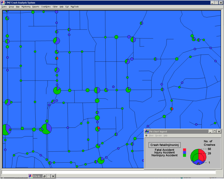
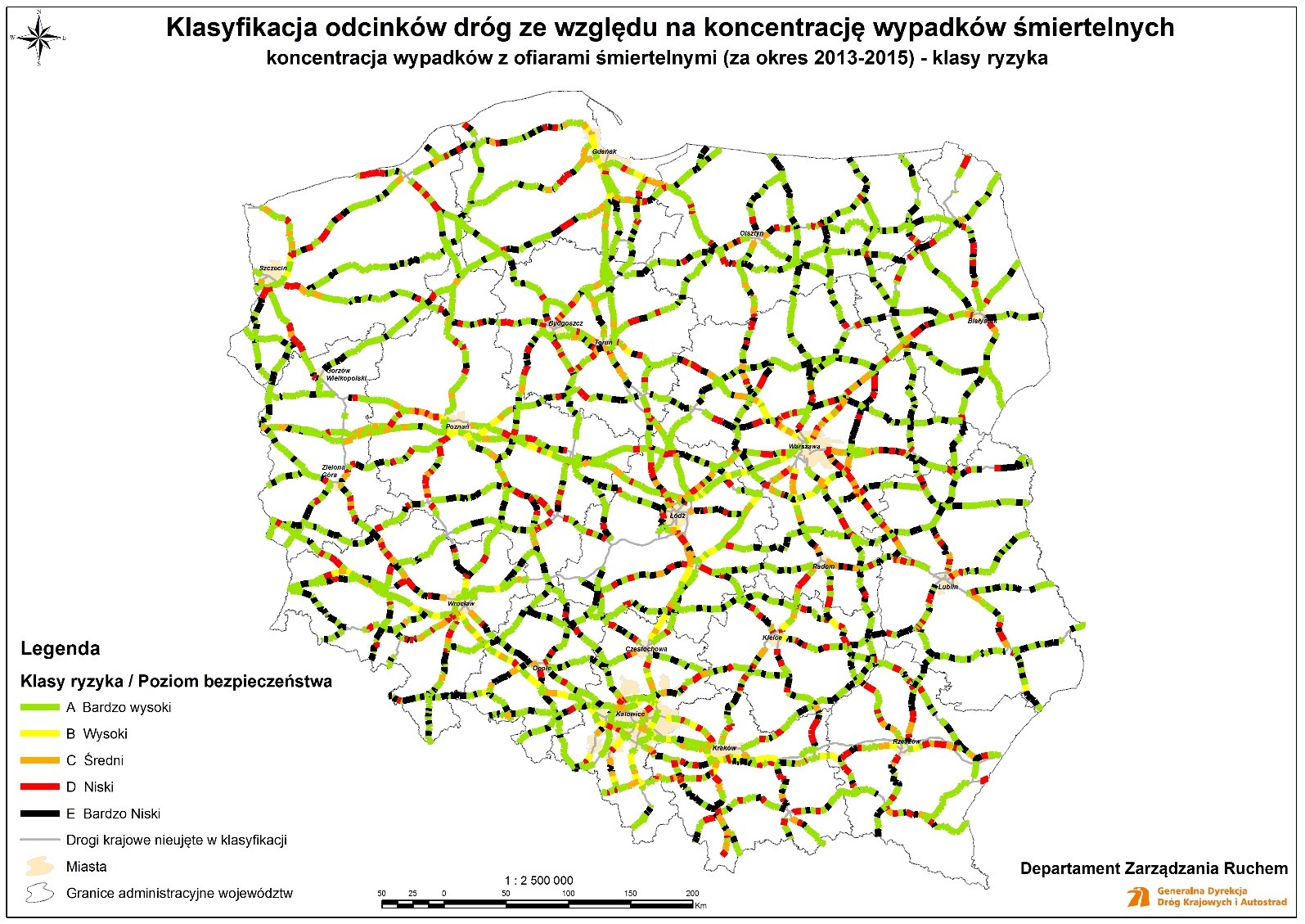
Figure 10.4 Shows an example of road safety levels map based on fatal accident crash risk concentration for national roads in Poland. More detailed maps for smaller regions together with maps representing fatal accident acceptance risk levels, costs density class risks and costs density acceptance levels are also available. All the maps are prepared in accordance with polish national regulations and Directive 2008/96/EC of the European Parliament and of the Council on road infrastructure safety management.
A ranked listing by crash frequency (i.e. highest crash numbers to lowest) can form the basis of an initial list of crash locations for further assessment. Usually a threshold level is selected, with sites above this threshold being assessed. The threshold is often set arbitrarily (e.g. five crashes per year), although it is preferable to take into account the available budget and/or a threshold involving crashes of a particular type (e.g. three pedestrian injuries per year).
Given the aim of road safety management is to minimise death and serious injury crashes, it is preferable to select sites for investigation based on crash severity. A common method of identifying high risk locations to take account of severity is to prioritise sites through a crash cost analysis. An effective method often used is called the Equivalent Property Damage Only (EPDO) Index, where crashes are weighted according to their severity. For instance, fatal crashes are assigned the highest cost/weighting per crash and property-damage-only (PDO) crashes (or minor crashes if PDO crash data is not collected) are assigned the lowest cost/weighting per crash. Although this is a relatively simple criterion to implement, it provides a basis for creating a shortlist of sites to be investigated further. As with the simple crash frequency-based approach, sites are ranked from highest cost to lowest cost, and a threshold is set for investigation.
A similar and yet more sophisticated method is the Relative Severity Index (RSI). Standard crash costs are assigned to crashes by crash type and road environment, as shown in the example in Table 10.1
| Crash costs for Victoria (AU$) | ||
|---|---|---|
| One-vehicle | Urban | Rural |
Pedestrian hit crossing road | 166,300 | 183,800 |
Hit permanent obstruction | 162,400 | 163,400 |
Hit animal on road | 102,300 | 79,500 |
Off road, on straight | 119,900 | 146,100 |
Off road, on straight, hit object | 177,500 | 206,600 |
Out of control, on road, on straight | 98,100 | 115,700 |
Off road, on curve | 146,900 | 175,900 |
Off road, on curve, hit object | 191,700 | 219,700 |
Out of control, on road, on curve | 120,100 | 112,110 |
| Two-vehicle | Urban | Rural |
Intersection (adjacent approaches) | 124,000 | 173,200 |
Head-on | 240,300 | 341,600 |
Opposing turns | 132,700 | 168,600 |
Rear-end | 64,200 | 109,700 |
Lane change | 88,500 | 132,800 |
Parallel lanes, turning | 79,900 | 104,600 |
U-turn/through | 124,600 | 135,600 |
Vehicles leaving driveway | 93,200 | 129,100 |
Overtaking same direction | 97,000 | 138,000 |
Hit parked vehicle | 112,500 | 202,700 |
Hit railway train | 384,400 | 559,100 |
Source: Adapted from Andreassen (2001).
These costs are calculated based on an analysis of the average crash severity of each crash type. It is important to note, however, that crash types and crash costs will differ between jurisdictions and countries. This method takes into account crash severity but places less emphasis on locations where a single fatal crash may skew outcomes because of its very high cost. Such an outcome might be the result of a ‘random’ event, never to be repeated. This is more likely on lower volume roads or road networks where fatal crashes are very infrequent. Of higher interest are locations, routes or areas where high severity events are likely to happen again in the future. Using average crash costs by crash type, crashes at each location can be assigned a crash cost, and then locations ranked by total crash costs.
In some cases, multiple identification methods are used. These use two or more of the methods identified above. Other selection criteria are also available. Some of these are quite complex, utilising crash prediction models and Empirical Bayesian (EB) methods (e.g. AASHTO, 2010). The EB method is currently considered one of the most reliable approaches for selecting crash locations. However, other approaches identified above can produce satisfactory outcomes, particularly when adequate weighting is applied to fatal and serious injury crash outcomes.
Crash sites can be assessed using statistical analysis to identify sites that are experiencing a statistically significant number of crashes in a set time period. This can be useful to distinguish between sites that are experiencing abnormally high crash rates and those that are merely experiencing variation due to chance.
The crash identification process allows for sites to be selected for further investigation. Using any of the abovementioned methods, a shortlist can be developed containing sites that will be considered for treatment. Available funding will limit the number of sites that can be treated, and so the shortlisted sites should be assessed through site inspections and an initial crash diagnosis to identify where cost-effective treatments can be implemented.

Diagnosing the contributing factors to crashes is the foundation for selecting an effective solution to a safety problem. To properly understand the problem, one must consider that:
Diagnosis of the contributing factors at a crash location is a four-step process:
These stages are discussed in further detail in the sections below.
Crash data is the most important information, and should be available from either the Police or road authority. The road agency may also have information on traffic volumes and any historical information about the site such as a layout plan, any changes in traffic patterns or land use, and any previous or current concerns raised by the community or stakeholders.
An effective way to identify groupings of certain crash types or other common factors at a location is to present the data as a frequency diagram, a factor matrix, or a collision diagram of the different crash types. A brief description of each of the analysis methods is provided below:
Typically, crashes are categorised within a crash database according to a certain crash type coding system. A common breakdown using 10 crash groupings is provided by PIARC (2013):
Other countries may use more or less crash type groupings. Given the importance of motorcycle fatal and serious injury in many countries, provision should also be made to record details of such crashes. This is typically recorded as the vehicle type as an additional variable to those provided above.
Crash type variables can be used to describe the type of the crashes in terms of parties involved, collision and vehicle/pedestrian manoeuvre just before the crash. Each variable, coded as a two digit number, describes the single specific crash type. In crashes where more than one type can be applicable, the corresponding number of variables should be selected.
A simple frequency histogram or diagram can be used to show the distribution of crashes and identify if any trends in crashes are appearing. This can be good for an initial assessment, but due to its simplicity, it should not be done as an alternative to a factor matrix or collision diagram.
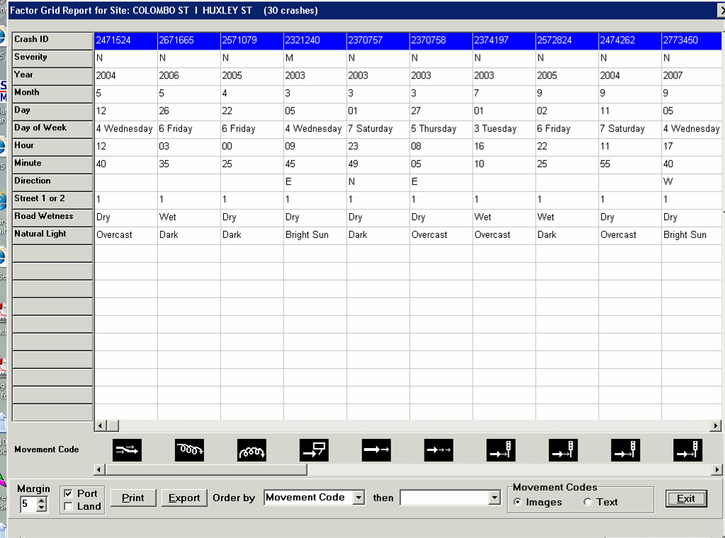
A factor matrix takes the frequency table approach one step further and considers additional factors such as the crash severity, year of the crash, direction of travel, type of road users, collision type, surface and lighting conditions, time of day, and day of week.
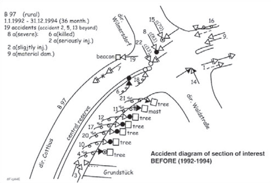
A collision diagram is an illustrative presentation of the crashes that have occurred at a location. Crashes are pinpointed on a diagram of the intersection or road section, showing the crash type (through standard symbols), the direction of travel, and other relevant information (e.g. the date, time of day, weather and lighting conditions). A number of software packages allow the automatic creation of these diagrams.
The main purpose of these data presentation types is to identify common contributing factors of crashes at a location. Note that there are normally several factors that lead to a crash. If there is no apparent dominant crash type that appears from the data, it can be very difficult to treat the site as it will be difficult for any one treatment to solve all the different issues at the site (speed management can be the exception to this, particularly in the elimination of high severity crash outcomes). Sometimes it can be helpful to look at the individual police crash reports for greater detail on the crash circumstances, as this might shed light on a common causal factor.
The main purpose of an inspection is to identify any environmental or traffic issues that may be contributing to crashes at the location. A site inspection can allow the crash investigation team to see the location through the eyes of the road user and observe the traffic behaviours. Additional data can also be collected, such as vehicle speeds, road features, parking restrictions and speed limits, as well as enable the team to assess any other characteristics of the surrounding road environment.
Where possible it is recommended that a team conduct the assessment, rather than an individual. A team approach will generally provide a more diverse range of opinions and ideas, as it is easier to generate these through group discussion. Team members might include an expert who is trained in road safety engineering and investigation of crash locations; and police and/or road agency staff, particularly those who are familiar with the location. The group may also include someone new to the crash investigation, but who has ideally undergone some form of training. This approach is essential to ensure development of skills for future crash investigators. Guidelines on Human Factors should be considered by those investigating sites (see Design for Road User Characteristics and Compliance), See also: NCHRP 600: Human Factors Guidelines for Road Systems.
It is recommended that the data analysis described above (e.g. production of a factor matrix and collision diagram) is circulated amongst the crash investigation team in the form of a preliminary report, prior to any site inspections.
A drive-through of the location should be undertaken to fully understand the road user experience. It is often useful to select someone unfamiliar with the area to do the driving so that they can experience the location as others would for the first time. Often there will be a need to drive through the site several times. An inspection on foot will also be required to more closely observe road user behaviour and site conditions. This will also allow for the collection of photos and notes, and to document any findings from the inspection. Sometimes it is also useful to inspect the site at different times of the day or days of the week to check for any variability in traffic flows or lighting/visibility conditions. For example, if a high number of night crashes have occurred, night inspections are essential.
Table 10.2 provides a list of possible contributing factors for different crash types (including those that contribute the most to fatal and serious injury outcomes) that should be considered by investigators during a site inspection. Although not listed, speed is linked to the frequency and severity of all crashes.
| Right angle crashes (intersection) | Turning crashes with oncoming crashes |
|---|---|
|
|
| Run-off-road crashes | Head-on crashes |
|
|
| Motorcyclist crashes | Cyclist crashes |
|
|
| Pedestrian crashes | Straight ahead rear-end crashes |
|
|
| Hit-fixed-object crashes | Railway level crossing crashes |
|
|
| Crashes involving a parked vehicle | Crashes involving U-turning vehicles |
|
|
| Lane changing and manoeuvring | |
| |
Before summarising the analysis in a report, consideration should be given to whether any additional information is required. For instance, if the crash analysis and/or site inspections suggest that there may be issues with skidding, then skid resistance testing could be undertaken.
A summary report should be prepared to clearly inform readers of the conclusions that were drawn from the analysis. This provides the basis from which treatment options are considered and selected. The report should include a description of the area or site, results from the data analysis (e.g. crash diagrams), observations from the site inspections, including possible contributing factors to crashes, comments on any identified common factors leading to crashes and possible remedial measures (see Intervention Options and Selection).
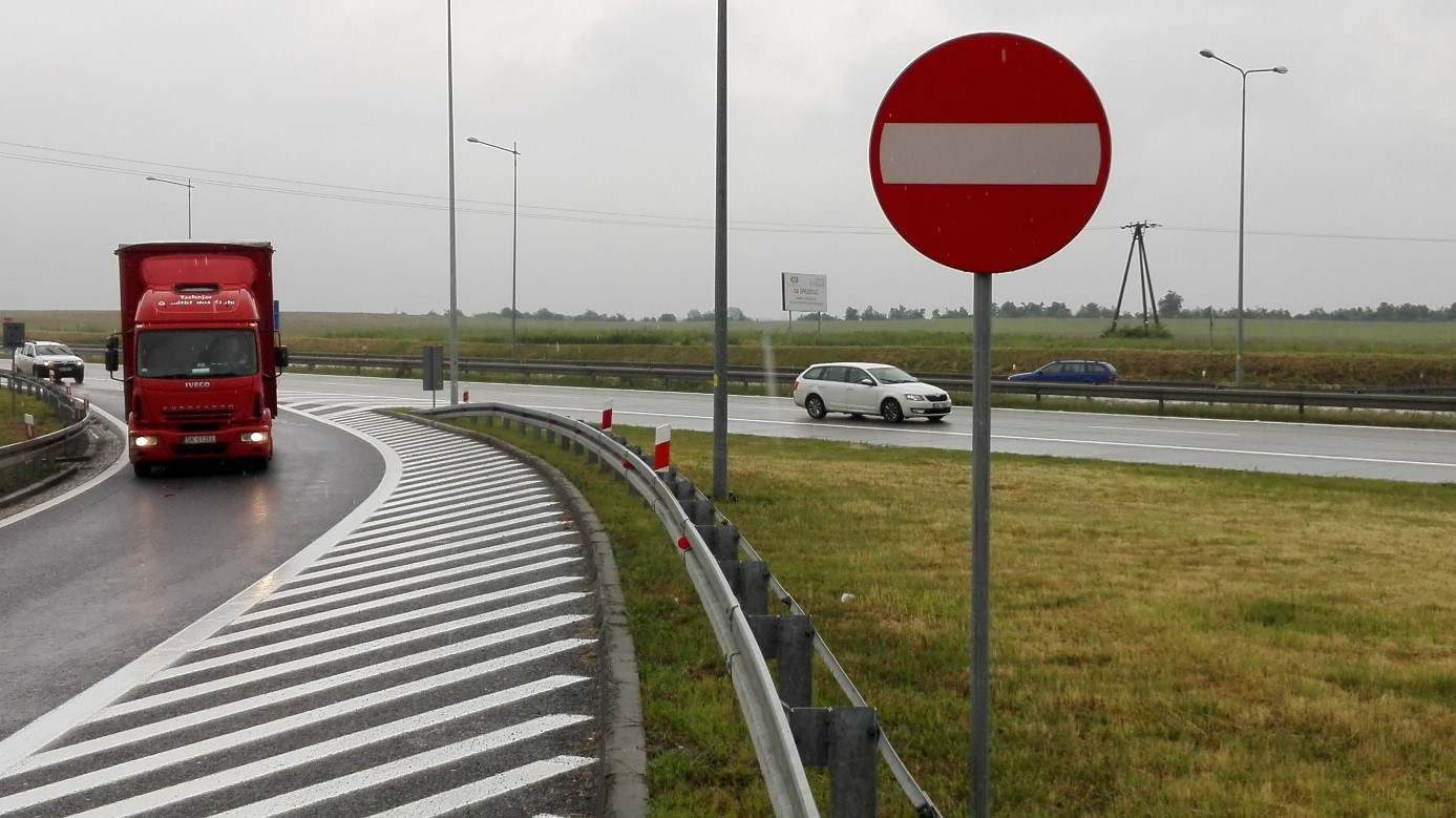
An example of a diagnosis, on motorways and expressways in were occasionally identified wrong-way drivers, “ghost riders”. The road authority recognised that the design should limit the possibility to travel the wrong way on roads where the opposite directions are physically separated. Some of the engineering solutions that were implemented long ago, were no longer recommended, but still exist and operate well when properly equipped with traffic signs and markings Ghost riders were also identified on new roads. After specially dedicated inspections with road traffic specialists and police, some additional signs minimising of the potential of unintentional wrong-way driving were installed. Solutions were adapted and placed on other new and existing roads as shown in the photo above. These actions removed the need to rebuild. This solution is used on new investments with practically zero additional costs.